What is this? This is my own implementation of the BlueRetro HW1 specification for the Sony PlayStation 1 and 2.
What does this thing do? It plugs into the PlayStation's controller ports and converts I/O signals from wireless into wired ones and vice-versa (transceiver). This allows you to use wireless Bluetooth controllers (such as the ones from the PS3-5, Wii-U, Switch, Xbox and a few more) with your PlayStation instead of the factory, wired ones.
Why did I build it instead of buying a commercial solution? Because I can, because I needed one, because it's cheaper, because it's more flexible and because it's funnier.
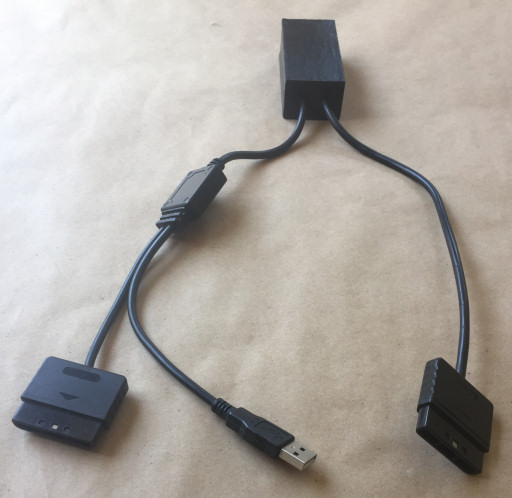
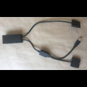
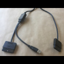
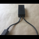
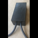
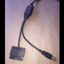
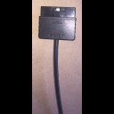
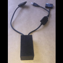
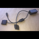
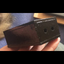
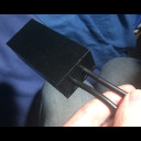
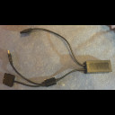
Here are a couple of overview photos before we dissect the adapter:
Software
The adapter is based on the BlueRetro software. This magnificient kernel (I like calling it like that, can also be identified as a firmware) handles all the Bluetooth stack, communication protocols, signal modulation, controller/console specifics and much more. It supports wireless config and update via Web-Bluetooth with a web browser.
I compiled my own binaries where I decreased the CPU clock, tweaked some of the options to better fit my hardware and finally modified the code to support one of my clone controllers.
I appreciate all the work that Jacques Gagnon and contributors have done for BlueRetro. As for my adapter: Finally a project where I don't have to program something, so to speak :)
Hardware
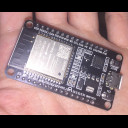
The adapter is powered by an ESP32 microcontroller. I'm using the most common, 4 MiB flash size, 30-pin DevKit with an ESP32-D0WD-V3 (revision v3.0) SoC. That's the classic ESP32-WROOM-32 module with the Xtensa dual-core LX6 microprocessor.
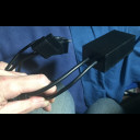
The adapter follows the HW1 schematics and I wired it to support two controllers simultaneously: One for each controller port in the console.
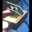
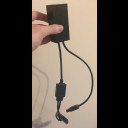
The controller plugs and cables came from non-working PS2 controllers so don't worry about me stripping and cutting the wires. One controller was counterfeit and the other was clearly an aftermarket one that as you can see in the photos, had a splitter box with an USB connector that allowed it to be used with a PC. I'll later cover the splitter box, its current use and other electrical stuff.
The build
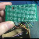
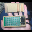
Internals (PCB)
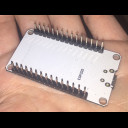
I designed my adapter with modularity, flexibility and repairability in mind. At the core is a self-made carrierboard, all wires are soldered to this board and it has a socket that allows ESP32 DevKits to be plugged/unplugged as required.
The design is very simple and clean. All cables and wires are sandwiched in the space between the carrierboard and the ESP32. Used wires come out of the back of the carrierboard and are soldered to their respective points. Unused wires are taped back and away. Everything is very well organized in there.
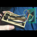
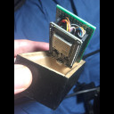
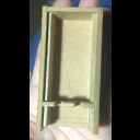
Once everything is installed, the carrierboard sits tightly on its holdplace. Notice that small chamber next to the main (PCB) chamber, that's a "buffer chamber". Cables are secured with a zip-tie in there, thus allowing them to move a couple of millimiters back and forth (cable buffer), while protecting everything from accidental pulls. The two openings between both chambers allow the cables to pull up and service the PCB.
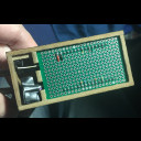
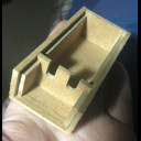
Externals (chassis)
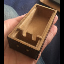
To hold everything together, I made a chassis out of MDF: A material I'm familiar with, a material that is cheap, flexible and easy to work with. Not enough resources to access a 3D printer, resin printer, laser cutter, CNC or anything of the like. I'm stuck with MDF and a cutting knife, pure handcrafting.
The design involves a dual-chamber, simple rectangular shape, compact enough to fit and hold the carrierboard in place on a couple of support walls, while leaving enough room for the ESP32 DevKit to be suspended in the main chamber and breathe (even if there are no holes). It also features a previously covered "cable buffer chamber".
The chassis uses no screws, everything is packed together like a puzzle and is accessible by a single top cover which is hold in place by pressure and with extra help from electrical tape.
Once all the faces are finished, I reinforce the material with carpenter's glue and then finally give it a black paint cover. Everything is ready for assembly now.
Power and USB stuff
I place this topic here, involving internal and external elements.
I setup the adapter as "bus powered", meaning that it is being powered directly by the PlayStation's 3.3v rail found in both of the controller ports which also happens to match the ESP32's 3.3v native power requirement. I even soldered both power lanes and both grounds to their respective points to ensure that the required amount of current is delivered because, in my own experience, I've found the ESP32 to be a bit temperamental when powered directly through 3.3v: There are these rare occasions where the ESP32 refuses to work past initialization or even to fully power on. It's just a matter of power cycling the PlayStation (just hit the power button twice on the console) and the issue is gone.
This brings me to USB and the splitter box. The ESP32 DevKit has its own 5v to 3.3v voltage regulator for power input and an USB-to-UART bridge for serial communication, both interfaced through a micro-USB port on the board. The reason why I kept the splitter box and USB connector is to have an alternative way to power the adapter via USB by plugging it directly to the PS2's USB port or even an external USB charger. It turns out that the optimal way to power the ESP32, in my opinion, is through 5v because the power delivery from the voltage regulator is stable and consistent, it just works.
Currently, USB power is not in use, it is sitting there just in case the ESP32 goes haywire. The USB data lanes are also isolated, they could be used to flash a new firmware via serial communication but that can also be conveniently done wirelessly.
Oh and the splitter box does not contain any USB logic, that was implemented in the controller itself. The box is just an electrical Y-splitter for the cables.
Final words
This thing rocks! No more cats going after my cables.
It works perfectly with a PS2 and a DualShock 3 controller at like 2~3 meters away. Bluetooth signal range doesn't seem to be heavily affected by the materials.
Temps are not a concern. ESP32 SoCs are very power efficient, generate little heat and have decent tolerance even under enclosed environments. Plus combined with whatever optimizations from a newer revision, an optimized firmware build and by not using the integrated voltage regulator; I'd say temps are pretty much under control.
One of the things I like the most is that the HW1 spec requires no console modding. You just create this adapter and use it with any number of consoles (one at a time).
I recommend you to build one of these things under whatever design you want. It is very easy, it is cheap, you'll have absolute control over every aspect and you'll have a lot of fun in the process.